ac generators; sinusoidal emfs (Sections 20.2 and 20.3)
resistance; Ohm's law; power (Sections 18.4 and 18.8)
emf and current (Sections 18.1 and 18.2)
period, frequency, angular frequency (Section 10.6)
capacitance and inductance (Sections 17.5 and 20.9)
vector addition (Sections 2.2 and 2.3; Appendix A.8)
graphical analysis of SHM (Section 10.7)
resonance (Section 10.10)
Mastering the Concepts
In the equation <a onClick="window.open('/olcweb/cgi/pluginpop.cgi?it=jpg::::/sites/dl/free/0073512141/663829/1.jpg','popWin', 'width=NaN,height=NaN,resizable,scrollbars');" href="#"><img valign="absmiddle" height="16" width="16" border="0" src="/olcweb/styles/shared/linkicons/image.gif"> (2.0K)</a> the lowercase letter (u) represents the instantaneous voltage while the uppercase letter (V) represents the amplitude (peak value) of the voltage. The quantity f is called the phase constant.
The rms value of a sinusoidal quantity is<a onClick="window.open('/olcweb/cgi/pluginpop.cgi?it=jpg::::/sites/dl/free/0073512141/663829/1_2.jpg','popWin', 'width=NaN,height=NaN,resizable,scrollbars');" href="#"><img valign="absmiddle" height="16" width="16" border="0" src="/olcweb/styles/shared/linkicons/image.gif"> (1.0K)</a> times the amplitude.
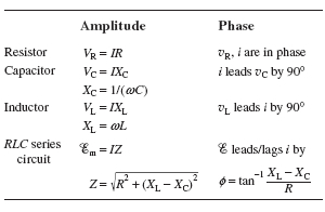
Reactances (XC, XL) and impedance (Z) are generalizations of the concept of resistance and are measured in ohms. The amplitude of the voltage across a circuit element or combination of elements is equal to the amplitude of the current through the element(s) times the reactance or impedance of the element(s). Except for a resistor, there is a phase difference between the voltage and current: <a onClick="window.open('/olcweb/cgi/pluginpop.cgi?it=jpg::::/sites/dl/free/0073512141/663829/Amp_phs.jpg','popWin', 'width=NaN,height=NaN,resizable,scrollbars');" href="#"><img valign="absmiddle" height="16" width="16" border="0" src="/olcweb/styles/shared/linkicons/image.gif"> (23.0K)</a>
The average power dissipated in a resistor is <a onClick="window.open('/olcweb/cgi/pluginpop.cgi?it=jpg::::/sites/dl/free/0073512141/663829/21_4.jpg','popWin', 'width=NaN,height=NaN,resizable,scrollbars');" href="#"><img valign="absmiddle" height="16" width="16" border="0" src="/olcweb/styles/shared/linkicons/image.gif"> (4.0K)</a> The average power dissipated in an ideal capacitor or ideal inductor is zero.
The average power dissipated in a series RLC circuit can be written <a onClick="window.open('/olcweb/cgi/pluginpop.cgi?it=jpg::::/sites/dl/free/0073512141/663829/21_17.jpg','popWin', 'width=NaN,height=NaN,resizable,scrollbars');" href="#"><img valign="absmiddle" height="16" width="16" border="0" src="/olcweb/styles/shared/linkicons/image.gif"> (4.0K)</a> where f is the phase difference between i(t) and <a onClick="window.open('/olcweb/cgi/pluginpop.cgi?it=jpg::::/sites/dl/free/0073512141/299144/ch21_Escript.jpg','popWin', 'width=NaN,height=NaN,resizable,scrollbars');" href="#"><img valign="absmiddle" height="16" width="16" border="0" src="/olcweb/styles/shared/linkicons/image.gif"> (0.0K)</a> The power factor cos f is equal to R/Z.
To add sinusoidal voltages, we can represent each voltage by a vector-like object called a phasor. The magnitude of the phasor represents the amplitude of the voltage; the angle of the phasor represents the phase constant of the voltage. We can then add phasors the same way we add vectors.
The angular frequency at which resonance occurs in a series RLC circuit is <a onClick="window.open('/olcweb/cgi/pluginpop.cgi?it=jpg::::/sites/dl/free/0073512141/663829/21_18.jpg','popWin', 'width=NaN,height=NaN,resizable,scrollbars');" href="#"><img valign="absmiddle" height="16" width="16" border="0" src="/olcweb/styles/shared/linkicons/image.gif"> (3.0K)</a> At resonance, the current amplitude has its maximum value, the capacitive reactance is equal to the inductive reactance, and the impedance is equal to the resistance. If the resistance in the circuit is small, the resonance curve (the graph of current amplitude as a function of frequency) has a sharp peak. By adjusting the resonant frequency, such a circuit can be used to select a narrow range of frequencies from a signal consisting of a broad range of frequencies, as in radio or TV broadcasting.
An ideal diode has zero resistance for current in one direction, so that the current flows without any voltage drop across the diode, and infinite resistance for current in the other direction, so that no current flows. Diodes can be used to convert ac to dc.
Capacitors and inductors can be used to make filters to selectively remove unwanted high or low frequencies from an electrical signal.