polarization by scattering and by reflection (Section 22.7)
Mastering the Concepts
A wavefront is a set of points of equal phase. A ray points in the direction of propagation of a wave and is perpendicular to the wavefronts. Huygens's principle is a geometric construction used to analyze the propagation of a wave. Every point on a wavefront is considered a source of spherical wavelets. A surface tangent to the wavelets at a later time is the wavefront at that time.
Geometric optics deals with the propagation of light when interference and diffraction are negligible. The chief tool used in geometric optics is the ray diagram. At a boundary between two different media, light can be reflected as well as transmitted. The laws of reflection and refraction give the directions of the reflected and transmitted rays. In the laws of reflection and refraction, angles are measured between rays and a normal to the boundary.
Laws of reflection:
The angle of incidence equals the angle of reflection.
The reflected ray lies in the same plane as the incident ray and the normal to the surface at the point of incidence.
Laws of refraction:
ni sin qi = nt sin qt (Snell's law).
The incident ray, the transmitted ray, and the normal all lie in the same plane—the plane of incidence.
The incident and transmitted rays are on oppositesides of the normal.
When a ray is incident on a boundary from a material with a higher index of refraction to one with a lower index of refraction, total internal reflection occurs (there is no transmitted ray) if the angle of incidence exceeds the critical angle <a onClick="window.open('/olcweb/cgi/pluginpop.cgi?it=jpg::::/sites/dl/free/0073512141/663831/23_5a.jpg','popWin', 'width=NaN,height=NaN,resizable,scrollbars');" href="#"><img valign="absmiddle" height="16" width="16" border="0" src="/olcweb/styles/shared/linkicons/image.gif"> (4.0K)</a>
When a ray is incident on a boundary, the reflected ray is totally polarized perpendicular to the plane of incidence if the angle of incidence is equal to Brewster's angle
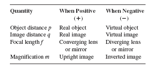
In the formation of an image, there is a one-to-one correspondence of points on the object and points on the image. In a virtual image, light rays appear to diverge from the image point, but they really don't. In a real image, the rays actually do pass through the image point.
Finding an image using a ray diagram:
Draw two (or more) rays coming from a single point on the object toward the lens or mirror.
Trace the rays, applying the laws of reflection and refraction as needed, until they reach the observer.
For a real image, the rays intersect at the image point. For a virtual image, extrapolate the rays backward along straight line paths until they intersect at the image point.
The easiest rays to trace for a mirror or lens are called the principal rays.
A plane mirror forms an upright, virtual image of an object that is located at the same distance behind the mirror as the object is in front of the mirror. The object and image points are both located on the same normal line from the object to the mirror surface. The image of an extended object is the same size as the object.
The magnitude of the transverse magnification m is the ratio of the image size to the object size; the sign of m is determined by the orientation of the image. For an inverted (upside-down) image, m < 0; for an upright (right-side-up) image, m > 0. For either lenses or mirrors,